Input Design Variables
The default values of the input design variables of all OpenAFPM tools correspond to a 2.4m rotor diameter 24V small wind turbine which is used frequently in rural electrification applications, while the values follow the design tips suggested in this section. Most locally manufactured small wind turbines follow the construction process presented in Hugh Piggott’s ‘Wind Turbine Recipe Book’ and so the designs created by the OpenAFPM tools are intended to by manufactured in the same way. If you would like to perform a design with the design values used in the ‘Wind Turbine Recipe Book’ then refer to the ‘Alternator Design’ section at the end of the book, which has some good design tips which can be used in combination with the design tips of this section.
Wind Speed
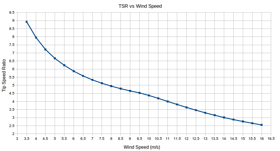
The cut-in wind speed is the wind speed at which the wind turbine will reach the battery voltage, or the grid-tie inverter’s low DC input voltage, and will start feeding energy to the system. This is typically at around 3m/s, but a stronger wind gust of about 4.5m/s will be required to start the blade rotor from stand still. The nominal or rated wind speed is usually chosen to be around 10m/s and corresponds to a high but frequent wind speed for which the generator will be designed to produce its rated power. Higher nominal wind speeds can be chosen but they will occur less frequently, so this is not a usual design approach, yet this will depend on the mean wind speed of the location. A more common design approach is to choose a lower nominal wind speed, when a large rotor is mounted on a small generator, in order to produce more power at lower wind speeds, which is good for low mean wind speed sites. In either case, when choosing a higher or lower rated wind speed than 10m/s during a design, the rated aerodynamic coefficient of the blades needs to be chosen accordingly in relation to the rated tip speed ratio. The furling system is designed in such a way so as to reduce power after the nominal wind speed is reached by yawing the blade rotor out of the wind, but at the nominal wind speed the yaw angle of the blade rotor to the wind direction will be close to zero.
Air Density
Always consider the altitude of the area that the wind turbine will be installed in, as differences in air density due to variations in altitude can produce significant changes in the power production of a wind turbine.
Tip Speed Ratio
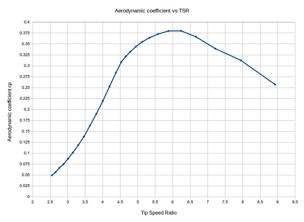
The rated tip speed ratio (TSR) will be determined by the RPM of the generator at the nominal wind speed which in turn will be determined by the generator rated voltage, which will depend on the battery voltage and the losses on the transmission cable between the wind turbine and the battery bank. The rated TSR will also define the rated value of the aerodynamic coefficient and this in turn will define the rated current at rated power production of the wind turbine. The diameter of the copper wire in the coils will be determined by the rated current so the choice of a realistic TSR for the nominal wind speed is important in order to operate at rated current with a reasonable efficiency. When directly connected to batteries the blade rotor will stall at a TSR of about 4.5 at a nominal wind speed of 10m/s, depending on the total resistive losses of the circuit. When connected through a maximum power point (MPP) converter the blade rotor will operate close to the optimal TSR (design TSR of the blades – 7 for most Recipe Book designs) and this will occur for a wide range of wind speeds. A low cost way of increasing the speed of the blade rotor (instead of using a MPP converter), and in this way also increasing the rated TSR, the rated aerodynamic coefficient of the blades and the rated generator power, is to increase the resistance in the power transmission cable. This can be achieved by using a thinner and thus cheaper transmission cable or for larger wind turbines, were losses are significant, introducing resistive heating elements in series with the transmission cable and making productive use of the heat. In the design tools, this can be achieved by increasing the transmission cable losses accordingly. The TSR value at the cut-in wind speed is usually between 8 and 9 for both direct battery and MPP connection, depending on the blade design, as the blades are spinning fast just before they start feeding some power to the batteries or to the grid-tie inverter.
Aerodynamic Coefficient
When directly connected to batteries the blade rotor will stall at a TSR of about 4.5 at 10m/s, depending on the circuit losses. The corresponding aerodynamic coefficient of the blades at this TSR would be about 0.3. When connected through a maximum power point converter the blade rotor will operate close to the optimal TSR which is the design TSR of the blades and this will occur for a wide range wind speeds. The corresponding aerodynamic coefficient of the blades at this TSR would be about 0.38, but this needs more investigation. The aerodynamic coefficient will determine the power produced by the generator at the nominal wind speed which in turn will determine the generator rated voltage and rated current. The diameter of the copper wire in the coils will be determined by the rated current so the choice of a realistic aerodynamic coefficient for the nominal wind speed is important in order to operate at rated current with a reasonable efficiency. The value of the rated TSR needs to be checked at the end of the design process in order to make sure that it corresponds to a value of the aerodynamic coefficient close to the one assumed in the beginning of the design.
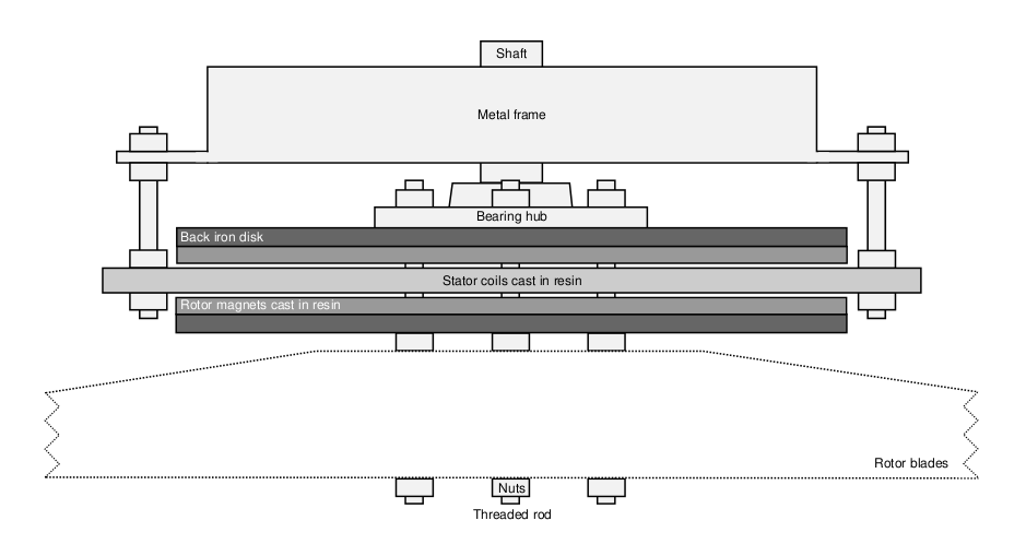
AFPM Rotor Topology
The Axial Flux Permanent Magnet (AFPM) generators that can be designed with these tools are all coreless, as in this way there is no cogging torque at low wind speeds and no core saturation and high inductances at high wind speeds. In addition, the stator coils are arranged in three phases and connected in star, as a three phase system allows better utilization of the stator area while giving a smooth torque output during operation. The generator topologies used in this design tool all carry the permanent magnets on the rotor of the generator while the coils are placed on the stator, as this allows the wires of the output phases to be connected directly to the transmission cables without the use of slip rings. The rotor-stator topologies that the user can choose from are a double rotor single stator configuration, a single rotor single stator configuration and a kind of hybrid of the two which is a double rotor single stator configuration yet one of the rotor disks does not carry any magnets and is there only to provide a low magnetic resistance path. The double rotor topology is the most common and is used for most blade rotors, yet the other two topologies can also be used, most frequently for smaller wind turbines, when larger magnets than what would be required are available.
Rotor Disk Thickness
When the rotor disk thickness is in ‘calculated’ mode and not defined by the user, then the result corresponds to the minimum disk thickness which will not produce saturation of the steel disk. This calculation though does not take into account the deflection of the rotor disks due to the attractive forces between the magnets in a double rotor, as this is not easy to calculate analytically and would need a structural finite element analysis. So when constructing the generator, and especially for large outer diameters and strong magnets, add intuitively a few millimeters to the result in order to produce minimal deflection of the disks at the outer radius. The simulation results will not be altered by doing this. The tradeoff for doing this is increasing the magnet rotor disk weight, which can be substantial for large wind turbines, so a balance needs to be found between the two. For larger turbines introducing holes in the disk can help in reducing its weight.
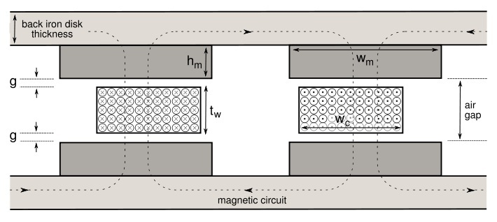
Magnet Grade
Several grades of Neodymium magnets can be used in the design tools and the higher the grade of the magnet the more flux density in the airgap. In addition, the closer the magnet rotors are to each other in a double rotor topology, the smaller the airgap between their opposing faces and so less resistance in the magnetic loop, which means more flux density in the airgap to induce voltages in the coils. So while trying to reduce the airgap between the rotors in order to use as much of the potential of the magnetic material as possible, there also needs to be enough space in the airgap to accommodate for the stator thickness and also for good mechanical clearance between the rotating and stationary parts of the generator, i.e. the magnet rotors and the stator coils. Typical mechanical clearance values are 3 or 4mm on either side of the stator, in order to accommodate for maintenance issues that might build up gradually over the years such as loose bearings in the hub, the stator warping from heat losses and Neodymium magnets swelling from corrosion. Both the thickness of the stator and the mechanical clearance, increase the axial spacing of the magnet rotors so they reduce the flux density in the airgap. If the mechanical clearance of a generator is increased then this will also increase the cut-in RPM and cut-in wind speed of the wind turbine, as more speed will be required to compensate for the reduced flux density in the generator air gap. On the other hand, this can be used, to an extent, to regulate the power matching of the blades to the generator and bring the blade rotor out of stall and more towards its design tip speed ratio, although choosing the correct cable size for connecting the wind turbine to the batteries will help more in this direction. The necessity for large airgaps is one of the disadvantages of axial flux machines over the very small airgaps of their radial flux counterparts. For this reason, large amounts of magnetic material are required in axial flux machines, i.e. large magnets, in order to produce the required flux density in the airgap. If the goal of a design is to increase the mechanical clearance of a generator while keeping the flux density in the airgap the same, then increasing the magnet grade is a possible solution. Increasing the magnet grade by one size up could allow for a couple of extra millimeters in the airgap.
Magnet Thickness
Increasing the thickness of the magnets allows for a larger airgap between their opposing faces for keeping the same amount of flux density in the middle of the airgap, i.e. in the middle of the stator for a double rotor topology. When the thickness of the stator needs to be increased in order to accommodate more copper for a given generator diameter, then increasing the magnet thickness will provide significantly more millimeters in the airgap than other measures, such as increasing the magnet grade for example. When altering the magnet thickness in order to increase the stator thickness, the ‘calculate’ mode can be chosen in the stator thickness input variable which will provide the user with a recommended value of thickness after the simulation is run. This value is an estimate and can be altered by increasing it or reducing it by one or two millimeters, but always run the simulation again to verify any changes made.
Number of Poles
The number of poles refers to the number of magnets on a single magnet rotor disk. By increasing or reducing the number of poles, magnets are spaced closer and further way from each other. A measure for this is the magnet width-to-pole pitch ratio (ai) which essentially describes how close the magnets are placed on the disk, with values ranging from 0 to 1. By increasing the number of poles while designing the generator for a given blade rotor, the efficiency of the generator is increased as more magnets and less copper are used to produce the same power. There is a limit though to how much the efficiency can increase because as the magnets get closer together they start leaking flux to each other, which essentially is lost from the airgap and counteracts the effect of introducing more magnetic material. In practice the efficiency will not increase significantly for values of ai above 0.6 for Neodymium magnets, which is when the distance between two adjacent magnets is about the same as their width. On the other hand reducing the number of poles will reduce the generator’s efficiency but will also reduce its cost as less magnets are used. A balance between the efficiency and cost can be found in designs with ai ranging from 0.4 to 0.5 for Neodymium magnets. In terms of size an increase in the number of poles will reduce the volume, mass and diameter of the generator. In generators using Ferrite magnets, which have lower flux densities that Neodymium magnets, a higher number of poles is necessary to produce the same power from a given rotor. So Ferrite magnet machines would find their balance of efficiency and cost in designs with ai ranging from 0.6 to 0.7, as Ferrite magnets are cheaper and need to be used in larger volumes.
Winding Type
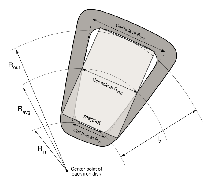
Three coil types can be used in the designs depending on the shape of the inner hole of the coil, namely rectangular coils, keyhole coils and triangular coils. A rectangular shape will have less flux linkage in the coils than a keyhole shape, and a triangular shape even less, but they will also have shorter end coil lengths. So there will be a play between the induced voltage and voltage drop due to losses on the coil resistance. Triangular coils, and keyhole coils to a lesser extent, will tend to produce designs of generators with smaller outer diameter so they are useful when volume and weight need to be reduced. In addition, keyhole and triangular coils will make better use of the available space in the stator when low flux density magnets such as Ferrite magnets are used, which will need to be packed closer together in the magnet rotors. Triangular coils will also allow for larger coil leg widths which can accommodate more turns in a given space. When volume is not issue and strong magnets such as Neodymium magnets are used, then the use of rectangular coils will reduce the internal resistance of the stator and in turn its thermal losses. In the design tools, when a rectangular coil is used then the coil hole has then same shape as that of the magnet. When a keyhole coil is used then the coil hole has the same radial length as that of the magnet, but the hole’s width is the same as the width of the magnet only at the average radius of the effective length of the generator which is at the middle of the coil’s radial length. On the other hand for triangular coils, the coil hole will have the same width as that of the magnet at the outer radius while at the inner radius it will have the width of the coil winder bolt. In the case of keyhole coils, the coil legs of consecutive coils will be touching throughout the effective length of the generator, whereas in rectangular coils the coils legs will be touching only at the inner radius and for triangular coils only at the outer radius. The simulation radius in the MagnAFPM and OptiAFPM tools is always the average radius of the effective length, ie the middle of the coil, but for the UserAFPM tool the simulation radius can be chosen between the inner, outer or average radius. This can provide more insight as to what happens at different parts of the generator, as the relative geometry of the stator and rotor change with the radius.
Coil Fill Factor
The fill factor can only be estimated in the preliminary design phase, as its actual value will depend on all the parameters of the coil, such as the number of turns, copper wire diameter, number of wires at hand, thickness of the coil and the shape of the coil’s hole. Yet some initial estimations can be made. For low voltage battery charging stators a good estimation of the fill factor is 0.57 for rectangular coils and 0.52 for triangular coils. This will depend with how many wires at hand you are winding with, so the above are good for one wire while 0.02 would need to be subtracted for every additional wire. So for example for triangular coils and three wires at hand an estimation for the fill factor would be 0.48. For high voltage stators fill factors of 0.65 can be used because of the thinner copper wire. The best thing to do is start your design with a guess, following the above or selecting ‘calculate’ mode and the above will be applied automatically. In the OptiAFPM tool ‘calculate’ mode is always used for the fill factor. Once the design is ready and you are about to construct the generator, make a test coil with the dimensions as specified in the design output variables and measure its fill factor at the middle of the side coil leg. Input the real fill factor in the design, run the simulation again and use the new dimensions for your construction. What will change is the diameter of the generator in order to accommodate coils with slightly larger or smaller coil leg width.
Heat Coefficient
The heat coefficient describes how much thermal energy (due to copper losses in the stator) the coils can dissipate from their surface area. A high value of the heat coefficient means trying to transfer large amounts of thermal energy through a small surface area, which will end up heating the stator fast at high temperatures. This will risk over-heating the stator if other measures are not taken, such as regulating the furling system to operate at lower wind speeds than the nominal. In order to avoid temperatures of more than 115 degrees Celsius in the stator, which will gradually degrade the enamel insulation of the copper wires, the heat coefficient should not exceed the value of 0.4W/cm2. Choosing low values of the heat coefficient will result in designs with higher efficiency and lower temperatures in the stator, but with larger generator diameter and heavier parts. Recommended values of the heat coefficient are below 0.35W/cm2 which will generally result in efficiencies of above 0.65 and will correspond to stator temperatures of about 100 degrees Celsius while operating at the nominal wind speed. During the operation of the wind turbine and depending on whether the stator is cooling down or warming up due to the changing wind, these values will vary by +/- 10 degrees Celsius.
Current Density
The current density describes how much current is allowed to pass through a specific cross-sectional area of copper wire. As the thermal losses of the copper wires in the stator depend on the current and the resistance in the coils, high values of current density for example will mean higher currents in thinner wires, which will translate in high current and high resistance and so high thermal losses. So the current density will define the amount of thermal losses in the stator and in turn the efficiency of the generator, as thermal losses are significantly higher than rotational losses and eddy current losses. How fast these losses can be dissipated will be determined by the heat coefficient based on the surface area of the stator, and this in turn will determine the stator temperature at the nominal wind speed. This means that high values of current density will produce less efficient generators at the nominal wind speed, yet for direct battery connection this is not a problem, as due to low rated TSR the blades will stall and the efficiency of the blade rotor will be significantly reduced at the nominal wind speed. On the other hand there is more energy to be harnessed in wind speeds closer to the mean wind speed of the site and it is then that an efficient generator is more useful. For systems operating with a MPP converter, such as grid-tied wind turbines, more efficient generators at the nominal wind speed can actually be useful, as the blades will be operating at high efficiencies and close to their design TSR. A more efficient generator can be designed by increasing the number of poles and/or by reducing the current density. For AFPM generators of wind turbines without any casing, as the ones designed using these tools, the current density can take values of up to 6.5A/mm2 for rated generator efficiencies of about 0.65. Higher values will reduce the efficiency of the generator further and, depending on the value of the heat coefficient, will risk over-heating the stator. Choosing a current density and a heat coefficient that produce generator designs with efficiencies of more than 0.7 is recommended, after having correctly associated the rated TSR with the corresponding aerodynamic coefficient from the graph in the relevant section of the design tips.
System Voltage
The user can choose different system voltages corresponding to battery banks of up to 96V and other high voltage applications up to 500V. The user can also choose the battery voltage at the nominal wind speed and observe how the rated TSR is affected by a higher battery voltage, such as equalizing charge (2.55V per cell) or float charge (2.25V per cell) voltages. In this case, and in order to observe changes in the power production of the wind turbine, the rated TSR will need to be associated with the appropriate aerodynamic coefficient using the graph in the relevant section of the design tips, having in mind that this graph has approximate values than depend on the blade design, on the furling system configuration and on the transmission cable resistance. While designing a generator using the MagnAFPM tool, a standard design approach would be to design for a half empty battery bank i.e. to set the battery voltage at the nominal wind speed to be the same as the system voltage, as is the default mode of the tool. This will provide a design for the generator at nominal wind speed around a lower voltage and higher current, as most times during strong winds the battery bank will quickly reach higher equalizing or float charge voltages and the wind turbine generator will operate at lower currents and lower stator temperatures. Again, during this phase of the design the rated TSR will need to be associated with the appropriate aerodynamic coefficient, using the graph in the relevant section of the design tips, or the general value of 0.3 for battery connected wind turbines can be used, which is also the default value.
Mesh Size
In all the finite element analysis (FEA) simulations of the OpenAFPM tools a 2D magnetostatic problem is solved using the magnetics processor of FEMM. In the MagnAFPM and OptiAFPM tools the generator geometry is drawn in FEMM and values of the flux density are calculated on the magnet surface and in the middle of the airgap in order to proceed with a generator design. In the UserAFPM tool the magnet rotors are rotated against the stator coils, with steps corresponding to a specific rotational speed while a three phase alternating current sequence is set in the coils. In this way the performance of a generator can be simulated while being driven by a specific rotor blade size and while feeding power in a battery bank or a grid-tie inverter. For each simulation step, a 2D magnetostatic problem is solved using a specific mesh size. The mesh size to be used in the finite element analysis will determine the accuracy of the results and also the computational time required to provide them. In the MagnAFPM tool the mesh size used is always fine during the design the generator, and then if the user chooses to continue with the UserAFPM tool and run a complete FEA, a choice between fine and automatic mesh are possible. In the UserAFPM tool, a choice between fine and automatic mesh are possible in order to run the FEA. In the OptiAFPM tool an automatic mesh is always used in order to reduce the computational time of the particle swarm optimization because it uses a small FEA for every design it considers. Overall, a fine mesh will produce more accurate results but for a longer computational time and an automatic mesh will produce less accurate results but for a shorter computational time. Depending on the design geometry the difference in the results between the two approaches of mesh size will vary, but in most cases the differences are small.
Particle Swarm Optimization
The Particle Swarm Optimization (PSO) algorithm works by having a population (called a swarm) of candidate solutions (called particles) who are guided by their own best known position in the search-space as well as the entire swarm's best known position. When improved positions are being discovered in every iteration (called generation) by minimizing an objective function, these will then come to guide the movements of the swarm. The process is repeated and by doing so it is hoped, but not guaranteed, that a satisfactory solution will eventually be discovered. It is important to remember that the PSO does not guarantee an optimal solution, and for this reason one should run the same optimization several times while keeping track of the results for each optimization. This can be done by choosing to repeat the process several times in the OptiAFPM input options. In the end result an average is taken from the positions of all the particles for each design variable that was optimized. If an optimization does not converge then try increasing the number of iterations. The OptiAFPM tool is useful if one wants to have a general overview of the dimensions of the permanent magnets for different designs with different performance criteria, such as reducing cost and mass while increasing efficiency.
Objective Function
The weights assigned to the performance criteria of Efficiency, Cost and Mass, make them more, or less important in the objective function to be minimized. The objective function is:
Weight*(1-Efficiency)*200+Weight*Cost/10+Weight*Mass+Penalty
A penalty is included in the objective function in order to account for designs that cannot be manufactured due to construction limitations. The user can choose to design a generator for an objective function that involves all three performance criteria (Efficiency, Cost and Mass) or only two of these or even a single one, by assigning zero values to the weights of the criteria that will not be used. When using a combination of two or three performance criteria to be minimized, it is important that their values in the objective function are of the same order of magnitude and ideally as close to each other as possible, so that small changes in one also influence the other. It is advised to run a test optimization, read the values of Efficiency, Cost and/or Mass terms and try for the next optimization to assign appropriate weights to them, so that their terms in the objective function have similar values. In this case they will be equally weighted, and if later you want to favor one performance criterion over another then you can vary their weights further.
Optimization Variables
Optimizations for two, three or four variables can be conducted using the OptiAFPM tool, but these are limited to specific combinations and design parameters in order to avoid complexity. When performing an optimization with two variables, this implies that the magnet radial length and the magnet width will the varied, while all other design parameters of the generator are specified by the user. In a similar way, when performing an optimization with three variables the magnet radial length, the magnet width and the magnet thickness will the varied, and when performing an optimization with four variables, the magnet radial length, the magnet width, the magnet thickness and the stator thickness will the varied. In all cases the coil fill factor is calculated according to the number of wires at hand and the coil type. For each variable, a maximum and a minimum value need to be specified. The user can start with a big search-space for each variable and after a few test runs of the tool, the search space can be made smaller in order to reduce the number of generations needed for the optimization to converge. The results of the optimization will give tables for the value of each optimization variable and for the objective function, by calculating an average for the values of each particle (a particle is a generator design) in the last generation. This will be displayed for each time the optimization was run. In addition to these outputs, the Efficiency, Cost and Mass of the last generator design that was performed during the last generation will also be given as an output, in order to get a general idea of the value range that the performance criteria are in. Also the Efficiency, Cost and Mass terms of the objective function are given for the last design in order to be able to provide the necessary weights in the next run. If the optimization has not converged then the results should not be considered and more generations should be added in the next run. At the end of every optimization the combined output graph needs to be checked along with the Penalty term of the objective function. If the designs considered in the optimization were realistic then the Penalty term should be zero and the combined output should be less than 5000, which is the value of the Penalty function for designs that cannot be built due to construction limitations. If the combined output graph displays results with values of 5000 and more then the user needs to consider the output warning messages of the simulation and alter the design inputs accordingly, until values of combined outputs appear that are close to the sum of the Efficiency, Cost and Mass terms of the objective function.
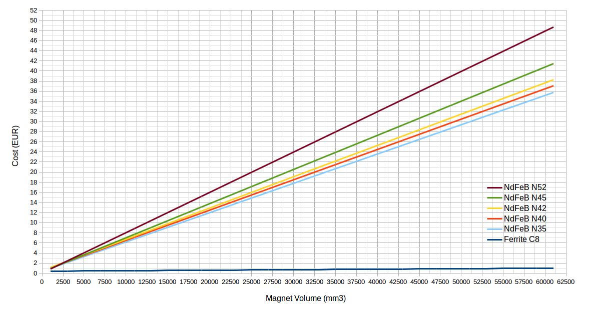
Magnet Cost
The cost of permanent magnets is calculated using the following relationships between magnet volume and cost, after market research for block magnets in quantities of about 40 pieces, from different suppliers on the internet as of January 2018. All optimizations that include the generator cost will be subject to chance according to the price of permanent magnets, but these prices have been stable for the past few years. Because of price changes and due to the nature of the PSO algorithm itself, optimizations using the OptiAFPM tool will provide qualitative results which can be used as design guidelines, rather than specific generator dimensions.
Construction Limitations
Several construction limitations are used in the OpenAFPM design tools in order to discourage users from manufacturing designs which might have problems in different stages of the manufacturing, operation or maintenance of a small wind turbine. When these construction limitations are reached the user is returned a message stating the reason that the design was not successful and some suggestions of what can be changed in order to improve it. Generator designs will not be simulated when: The mass of one magnet rotor is more than 100kg (this will come into effect when designing larger machines which will have weight limitations), the magnets and/or coils are overlapping at the inner radius of the generator, the hole of the coil at the inner radius is less than 5mm, the leg width of the coil is more than three times the thickness of the stator, the thickness of the coil is more than twice the leg width of the coil, the coils require more than 8 wires at hand of 1.9mm copper wire diameter to be made and when the efficiency of the generator is below 0.55, when the heat coefficient is above 0.55 and when the current density is above 8, as all of these will create temperatures in the stator above 145 degrees Celsius. In addition to these limitations, a warning is given to the user when the generator efficiency is below 0.65, when the heat coefficient is above 0.4 and when the current density is above 6.5, but the generator design will be simulated. If for any reason these limitations pose a problem to your designs please contact us.
Design Process
In the following flow chart the basic generator design process for all OpenAFPM tools is described. It is an iterative process during which the variables in bold are initialized in the beginning of the process and then they are updated during the end of the process, for every iteration. The process continues until these variables converge to a single solution.
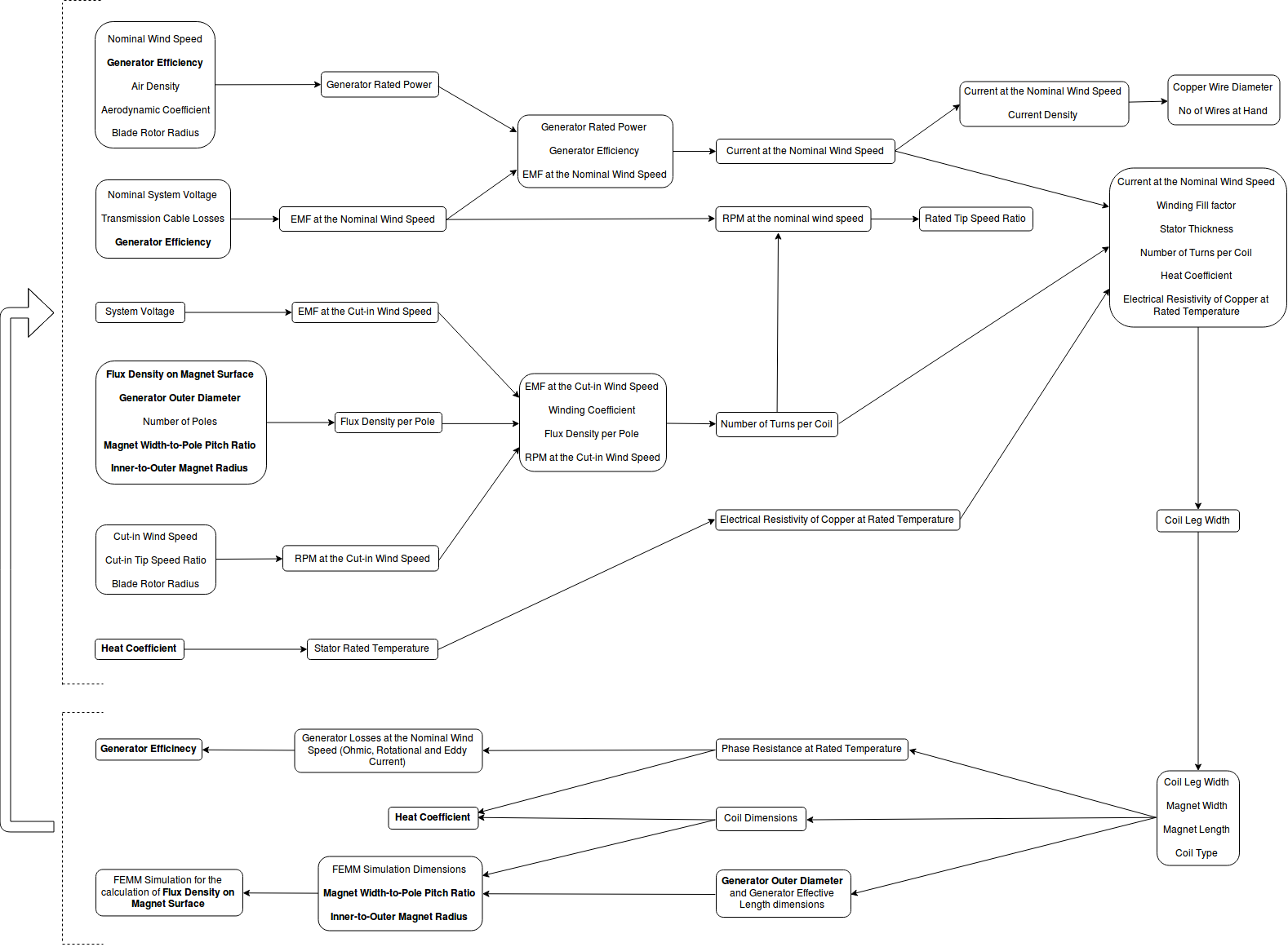
In the UserAFPM tool a variation of the above process is used but in this case most of the generator geometry is given by the user along with the generator rated operating conditions. Once the generator is drawn in FEMM and the flux density on the magnet surface is calculated, as in the above process, then the generator rotor is turned at rated RPM, for no load and at rated current in the winding. The user can also get results for RPM and current values in between these two states by specifying an appropriate RPM and current step. For every simulation step, the size of which will depend on the RPM and generator diameter, the flux linkage of each coil and the force in the air gap are measured in FEMM. From these measurements, the induced EMF and the torque are calculated respectively, for the specific set of speed and current that the simulation is running at. Later these will be used to produce results for the performance of the generator and they will be displayed in the simulation outputs either with a (Torque) or a (Flux Linkage) term in order to show from which measurement the results were derived. Results which are calculated using analytical equations are followed by a (Calculated) term.
Preliminary Generator Design
When designing the generator of a specific blade rotor size for the first time, then the following preliminary design process can be followed:
-
Use the OptiAFPM tool to get a rough idea of the possible magnet dimensions to be used in the design. Use a large search-space for all variables and run the tool several times, initially with few particle generations to save computational time, while adjusting the weights of the performance criteria each time so that they match, or favoring some over others, and checking that the generator designs do not fall into construction limitations with high penalties. Once the design is set increase the number of particle generations and check that the simulation results converge to single solutions for all variables.
-
Use the MagnAFPM tool for an average of the magnet dimensions found in OptiAFPM and set all options to ‘calculate’ mode in order to find out the stator thickness and back iron thickness. Check the efficiency of the design and decide whether to increase or decrease the number of poles. Run MagnAFPM again, this time with a quick UserAFPM simulation with the automesh option, to check the efficiency and rated power in more detail.
-
Use the OptiAFPM tool again, this time using the number of poles, stator thickness and magnet rotor thickness found in the previous runs of MagnAFPM. Use a large search-space for all variables and run the tool several times, adjusting the weights of the performance criteria each time so that they match or favoring some over others. Repeat the process several times, using the appropriate option in the OptiAFPM tool, in order to get an average for the magnet width and magnet length that optimize the defined performance criteria and their weights.
-
Use the MagnAFPM tool again, and this time input the more accurate results of the OptiAFPM tool. Run MagnAFPM to check the design and then choose the option to run a UserAFPM simulation with a fine mesh this time, to check the efficiency, rated power and the general performance of the design in more detail.
-
This should conclude the preliminary design of the generator, but further study of the design is advised by using the tools again and carefully checking all aspects of the generator, while also slightly varying some of its parameters to search for improvements.
Blade Rotor Radius
The blade rotor in all OpenAFPM tools can take values for its radius (blade length) from 0.6 to 5m, which would correspond to wind turbines of about 150W to 10kW of rated power at 10m/s. The OpenAFPM tools have been used for several generator designs constructed in the NTUA, which have been tested for their accuracy with errors of less than 5%. The largest machine constructed with these tools has been a 6m rotor diameter wind turbine which produced about 5kW at its rated RPM. For designs with blade rotor radius larger than 3m the OpenAFPM tools have not been verified, so if you are planning to construct a larger wind turbine we would advise you look over your designs carefully, make a test coil to verify the generator diameter and use an appropriate furling system to regulate power after the nominal wind speed. You can also consult us to assist you in the process, but in any case do let us know how everything went if you go down this road.
References
Some references on locally manufactured small wind turbines and on the design approaches used in the OpenAFPM tools:
K. Latoufis, T. Pazios and N. Hatziargyriou, ‘Locally Manufactured Small Wind Turbines: Empowering communities for sustainable rural electrification’, IEEE Electrification Magazine, Vol. 3, No. 1 , March 2015 - Article
K. Latoufis, A. Troullaki, T. Pazios and N. Hatziargyriou, ‘Design of Axial Flux Permanent Magnet Generators Using Various Magnetic Materials in Locally Manufactured Small Wind Turbines’, XXIIth International Conference on Electrical Machines (ICEM’2016), September 2016 - Article
K. Latoufis, A. Rontogiannis, V. Karatasos, P. Markopoulos and N. Hatziargyriou, ‘Thermal and Structural Design of Axial Flux Permanent Magnet Generators for Locally Manufactured Small Wind Turbine’, XIIIth International Conference on Electrical Machines (ICEM), 2018 - Article
G. Messinis, K. Latoufis, N. Hatziargyriou, ‘Design, Construction and Cost Minimization of a Coreless Axial Flux Permanent Magnet Generator for Small Wind Turbine Applications’, 7th Int. PV-Hybrid and Mini-Grid Conference, Bad Hersfeld, Germany, 10-11th April 2014 - Article
G. Messinis, K. Latoufis, N. Hatziargyriou, ‘Design aspects of coreless axial flux permanent magnet generators for low cost small wind turbine applications’, EWEA 2014, Barcelona, Spain, March 2014 - Article
K. Latoufis, G. Messinis, P. Kotsampopoulos, N. Hatziargyriou ‘Axial flux permanent magnet generator design for low cost manufacturing of small wind turbines’, Wind Engineering, Volume 36, No. 4, 2012 - Article
H. Piggott, ‘A Wind Turbine Recipe Book: The Axial Flux Windmill Plans’, Self-publication, 2009 - Book